以下の内容はhttps://gijin77.blog.jp/archives/2025-01.htmlより取得しました。


◆aitendo 2025福箱に入っていた「学習シールド [GK-SLD1]」を「ESP32でいいの」に
 載せて使ってみた。
 学習シールド
 ◆「ESP32でいいの」については、下記ブログ内記事を参照して下さい。
 ・aitendo ESP-32でいいの★ESP-32★ [R32D1] ESPなし基板へESP32を付けてみた

1.aitendo 学習シールド [GK-SLD1]のURL
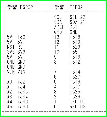
 学習シールド [GK-SLD1]

 ①ピン配置
 (「ESP32でいいの」でIO0に接続されている為、赤〇のピンをカットしないと
  書き込みが出来ません。)
 MultiFuncShield_pin

 ②回路図
 MultiFuncShield_回路図

 ➂「ESP32でいいの」と「学習シールド」とのピン対応
 学習シールドとESP32のピン対応

2.参考サイト
 ①Arduino Multi-function Shield を使ってみた
 ②コヒーシブコンピューティング

3.(参考)7セグLEDを使った時計/カレンダ-表示スケッチを下記に示します。
 ①Multi-function Shield用のライブラリは、ESP32に対応していなかったのでライブラリを
  参考に独自に表示ルーチンを作成しました。
 ②スケッチ概要
  1.7セグLEDをダイナミック表示させるため別タスクで常時実行
  2.時計を6秒、カレンダーの西暦年を2秒、月日を2秒繰り返し表示
  3.時計表示時、時分間のドットと4つのLEDを0.5秒間隔で点滅表示
  4.時刻は、WiFiを使いNTPに接続して取得
 
 ➂実行様子
 カレンダー時計表示
  
 ④スケッチ

//ESP32-clock.ino
//V2025/01/31
//blog URL:https://gijin77.blog.jp/archives/43583194.html

#include <WiFi.h>
#include <time.h>

#define BLED 2 //ESP32でいいの
#define ON   1
#define OFF  0
#define LED_1_PIN     18 //13
#define LED_2_PIN     19 //12
#define LED_3_PIN     23 //11
#define LED_4_PIN      5 //10
#define POT_PIN        3 //0
#define BEEPER_PIN    25 //3
#define LATCH_PIN     17 //4
#define CLK_PIN       14 //7
#define DATA_PIN      12 //8
//***************************************************************************
const char *ssid = "IO_Net_2G"; //put your Wi-Fi SSID
const char *password = "1234567890"; //put your Wi-Fi password
const char *timeZone = "JST-9";
const char *server = "pool.ntp.org"; //"ntp.nc.u-tokyo.ac.jp"
char week[7][4]={"Sun","Mon","Tue","Wed","Thu","Fri","Sat"};
struct tm localTime;
int hour   = 0;
int minute = 0;
int second = 0;
int day  = 0;
int mon  = 0;
int year = 0;
int wday = 0;
int bday = 0;
int colon= 0;
unsigned long ps_Time = 0;
unsigned long co_Time = 0;

byte data7[]={0x7F,0xF8,0xF8,0xF8,0xF8};
const byte LED[] = {LED_1_PIN, LED_2_PIN, LED_3_PIN, LED_4_PIN};
// Segment byte maps for numbers 0 to 9 
const byte SEGMENT_MAP_DIGIT[] = {0xC0,0xF9,0xA4,0xB0,0x99,0x92,0x82,0xF8,0X80,0X90};
// Segment byte maps for alpha a-z 
const byte SEGMENT_MAP_ALPHA[] = {136, 131, 167, 161, 134, 142, 144, 139 ,207, 241, 182, 199, 182, 171, 163, 140, 152, 175, 146, 135, 227, 182, 182, 182, 145, 182};
// Byte maps to select digit 1 to 4 
const byte SEGMENT_SELECT[] = {0xF1,0xF2,0xF4,0xF8};
//7seg4桁ダイナミック表示処理
void Disp7seg_Task(void *parameter) {
  while (1) {
    for(int seg=0;seg<4;seg++) {
      delay(1);
      WriteValueToSegment(seg,data7[seg]);
    }
  }
}
//**********************************************
void setup(){
	Serial.begin(115200);
  delay(2000);
  Serial.println();
  Serial.println("<Program Start>");
  pinMode(BLED, OUTPUT);
  digitalWrite(BLED, HIGH);
  initShield();
  initialize(); //WiFi接続
  xTaskCreatePinnedToCore(Disp7seg_Task, "Disp7seg_Task", 4096, NULL, 1, NULL, 0);
  delay(3000);
}
void loop() {
  get_time();         //1秒毎に時刻取得
  update_clock();     //時計表示の更新
  if ((second%10)>6) {
    update_calendar();//カレンダー表示の更新
  }
}
//**********************************************
void get_time() { //1秒毎に時刻取得
  if (millis() - ps_Time > 1000) { 
    if (getLocalTime(&localTime)) {
      hour   = localTime.tm_hour;
      minute = localTime.tm_min;
      second = localTime.tm_sec;
      day    = localTime.tm_mday;
      mon    = localTime.tm_mon+1;
      year   = localTime.tm_year+1900;
      wday   = localTime.tm_wday;
      //Serial.printf("%04d/%02d/%02d(%s) %02d:%02d:%02d  \n", year,mon,day,week[wday],hour,minute,second);
    } else {
      Serial.println("時間を取得できませんでした。");
    }
    ps_Time = millis();
  }
  if (millis() - co_Time > 500) { 
    colon=!colon;
    int on;
    if (colon) { on=LOW; } else { on=HIGH; }
    writeLed(0,on);writeLed(2,on);
    writeLed(1,!on);writeLed(3,!on);
    co_Time = millis();
  } 
}
void update_clock() { //時計表示の更新
int h1,h0,m1,m0,s1,s0;
  h1=hour/10;   h0=hour%10;
  m1=minute/10; m0=minute%10;
//  s1=second/10; s0=second%10;
    data7[0]=SEGMENT_MAP_DIGIT[h1];
    if (colon) {data7[1]=SEGMENT_MAP_DIGIT[h0]&0x7F;} //ドット追加
    else       {data7[1]=SEGMENT_MAP_DIGIT[h0];}
    data7[2]=SEGMENT_MAP_DIGIT[m1];
    data7[3]=SEGMENT_MAP_DIGIT[m0];
}
void update_calendar() { //カレンダー表示の更新
int y3,y2,y1,y0,m1,m0,d1,d0;
  y3=year/1000; y2=(year % 1000) / 100;
  y1=(year % 100) / 10; y0=year%10;
  m1=mon/10; m0=mon%10;
  d1=day/10; d0=day%10;
  for(int n=0;n<4;n++) {writeLed(n,HIGH);}
  data7[0]=SEGMENT_MAP_DIGIT[y3];
  data7[1]=SEGMENT_MAP_DIGIT[y2];    
  data7[2]=SEGMENT_MAP_DIGIT[y1];
  data7[3]=SEGMENT_MAP_DIGIT[y0];   
  delay(2000);
  data7[0]=SEGMENT_MAP_DIGIT[m1];
  data7[1]=SEGMENT_MAP_DIGIT[m0]&0x7F; //ドット追加  
  data7[2]=SEGMENT_MAP_DIGIT[d1];
  data7[3]=SEGMENT_MAP_DIGIT[d0];   
  delay(2000);
}
void initShield() { //各ポートを初期設定
  pinMode(LED[0], OUTPUT);digitalWrite(LED[0], HIGH); //LED消灯
  pinMode(LED[1], OUTPUT);digitalWrite(LED[1], HIGH);
  pinMode(LED[2], OUTPUT);digitalWrite(LED[2], HIGH);
  pinMode(LED[3], OUTPUT);digitalWrite(LED[3], HIGH);
  pinMode(LATCH_PIN,OUTPUT);digitalWrite(LATCH_PIN, LOW);
  pinMode(CLK_PIN  ,OUTPUT);digitalWrite(CLK_PIN  , LOW);
  pinMode(DATA_PIN ,OUTPUT);digitalWrite(DATA_PIN , LOW);
  pinMode(BEEPER_PIN,OUTPUT);digitalWrite(BEEPER_PIN, HIGH);
}
byte AsciiToSegmentValue (byte ascii) { //アスキー文字を表示データへ変換
  byte segmentValue = 0xB6; //182;
  if (ascii >= '0' && ascii <= '9') {
    segmentValue = SEGMENT_MAP_DIGIT[ascii - '0'];
  } else if (ascii >= 'a' && ascii <='z') {
    segmentValue = SEGMENT_MAP_ALPHA[ascii - 'a'];
  } else if (ascii >= 'A' && ascii <='Z') {
    segmentValue = SEGMENT_MAP_ALPHA[ascii - 'A'];
  } else {
    switch (ascii) {
      case '-':
        segmentValue = 0xBF; //191;
        break;
      case '.':
        segmentValue = 0x7F; //127;
        break;
      case '_':
        segmentValue = 0xF7; //247;
        break;
      case ' ':
        segmentValue = 0xFF; //255;
        break;
    }
  }
  return segmentValue;
}
void WriteValueToSegment(byte Segment, byte Value) { //各セグメントに表示
  digitalWrite(LATCH_PIN, LOW);
  for (uint8_t i = 0; i < 8; i++)  {
    digitalWrite(DATA_PIN , !!(Value & (1 << (7 - i))));
    digitalWrite(CLK_PIN  , HIGH);
    digitalWrite(CLK_PIN  , LOW);
  } 
  for (uint8_t i = 0; i < 8; i++)  {
    digitalWrite(DATA_PIN ,!!(SEGMENT_SELECT[Segment] & (1 << (7 - i)))); 
    digitalWrite(CLK_PIN  , HIGH);
    digitalWrite(CLK_PIN  , LOW);
  } 
    digitalWrite(LATCH_PIN, HIGH);
}
void writeBeeper (byte value) { //ブザーON/OFF
  digitalWrite(BEEPER_PIN, value);
}
void writeLed(byte ledIdx, byte value) {//各LEDのON/OFF
  if (ledIdx>3) return;
  digitalWrite(LED[ledIdx], value);
}
void initialize() {  //Wi-Fi接続
  WiFi.begin(ssid, password);
  Serial.printf("[%s] Wi-Fiに接続中",ssid);
  int retryCount = 0;
  while (WiFi.status() != WL_CONNECTED) {
    Serial.print(".");
    if (retryCount > 30) { //15秒以上接続不良の為リスタート
      Serial.println("");
      Serial.println("Wi-Fiに接続できませんでした。");
      Serial.println("リスタートします。");
      ESP.restart();
    }
    delay(500);
    retryCount++;
  }
  Serial.println("");
  Serial.printf("[%s] Wi-Fiに接続しました。\n",ssid);
  configTzTime(timeZone, server);//NTPサーバーに接続
}


以上


ブログトップへ

◆aitendo 2024福箱に入っていたESP-32でいいの★ESP-32★ [R32D1] ESPなしに
 「ESP32-WROOM-32E」を取り付け使えるようにしました。
 本来は、「ESP32-WROOM-32」を取り付ける設計ですが、価格もちょっと安く
 フラッシュメモリは16MB搭載しているのでこちらにしました。
 esp32deiino

1.aitendo ESP-32でいいの★ESP-32★ [R32D1] のURL
  ESP-32でいいの★ESP-32★ [R32D1]

 ①ピン配置
 ESP32-WROOM-32E_

2.参考までに秋月電子でのURLとピンアサインとデータシートです。
  「ESP32-WROOM-32E」530円
  「ESP32-WROOM-32」550円

 ◆因みに「ESP32-WROOM-32E」は17ピンから22ピんのSD関連がNCとなっています。

 ①ESP32-WROOM-32E
  ESP32-WROOM-32E 16MBデータシート
 ESP32-WROOM-32E_pin

 ②ESP32-WROOM-32
  ESP32-WROOM-32データシート
 ESP32-WROOM-32_pin

3.動作確認
 ◆失敗談ESP32を半田付けする時、右側のピンソケットこてがあたり溶かして
  しまいました。なのでピンソケットを交換しました。
  手持ちに白のピンソケットが無かったので不格好ですが緑のものにしました。

 ①定番のLチカです。LEDは、ESP32devkit等と同じGPIO2に接続されていました。
  ◆青が電源表示、赤が内蔵LEDです。
 esp32deiino_完成時
 
 ②次に学習シールドを繋いでみました。下記ブログ内記事を参照して下さい。
  ・aitendo 学習シールド [GK-SLD1]をESP32で使用してみた
 学習シールド
 
以上


ブログトップへ

◆ESP32-C3 Super Miniを入手したので定番のLチカをしてみました。
 これには、GPIO8に青色LEDが接続されています。
 GPIO8を「LOW」に落とすと点灯します。
 esp32-c3_Lチカ
 
 ◆詳しくは、下記サイトが参考になります。
  ESP32-C3 Super Mini

1..ピンアサインと回路図(参考)
 ①ピンアサイン
 esp32c3supermini_pin
 ②回路図
 esp32c3supermini_回路図

2.シリアル出力をする為のIDEの設定
 C3_IDE_設定

 ◆ESP32-S3/C3でシリアル出力に関して詳しく調べて有る下記サイトが参考になります。
 Inside: ESP32-S3のSerialの謎を解き明かそう!

3.スケッチ

//ESP32-C3_Ltika.ino
//V2025/01/28
//blog URL:https://gijin77.blog.jp/archives/43554466.html

#define LED 8 //ESP32-C3 SuperMini

void setup(){
	Serial.begin(115200);
  delay(2000);
  Serial.println();
  Serial.println("<Program Start>");
  pinMode(LED, OUTPUT);
}

void loop() {
  digitalWrite(LED, LOW);  //LOWで点灯
  Serial.println("LED 点灯");
  delay(1000); 
  digitalWrite(LED, HIGH);
  Serial.println("LED 消灯");
  delay(1000);
 }


以上


ブログトップへ

◆秋月電子の店舗限定アウトレットセールにて200円で販売されていたものを
 ESP32S3 SuperMini で1個だけ使って時計表示してみました。
 AkiMatrix_clock

 ◆フォントを使ったデモや回路図、説明書等は、下記ブログ内記事を参照して下さい。
 ・秋月電子 32x16ドットLED マトリクス表示装置でフォント表示させてみた

1.表示ドットが限られている為数字用だけの3x5,4x7のファントを作成しました。
 今回のフォントは、スケッチ内に収めました。

2.秋月のドットマトリクス表示用ライブラリは、前回のままです。
 ◆前の記事の「AkiMatrix.h」「AkiMatrix.cpp」をお使いください。

3.スケッチ(保障無しの自己責任で)
 ①曜日表示は、簡易的に最上段に2ドットで日曜から土曜まで表示しています。
  日曜日は、x=18,19 y=0の位置です。土曜日は、x=30,31 y=0の位置です。

//AkiMatrix_clock.ino
//V2025/01/25 by JK1VCK
//blog URL:https://gijin77.blog.jp/archives/43526283.html
//  Hello Matrix ライブラリ
//  by arms22 <http://arms22.blog91.fc2.com/>

#include "AkiMatrix.h"
#include <WiFi.h>
#include <time.h>

//***************************************************************************
static const unsigned char font_no_s[][3] = { //3x5 font
 {0xF8, 0x88, 0xF8}, // 0
 {0x00, 0x00, 0xF8}, // 1
 {0xB8, 0xA8, 0xE8}, // 2
 {0xA8, 0xA8, 0xF8}, // 3
 {0xE0, 0x20, 0xF8}, // 4
 {0xE8, 0xA8, 0xB8}, // 5
 {0xF8, 0xA8, 0xB8}, // 6
 {0x80, 0x80, 0xF8}, // 7
 {0xF8, 0xA8, 0xF8}, // 8
 {0xE8, 0xA8, 0xF8}, // 9
 {0x10, 0x20, 0x40}, // /
}; 
static const unsigned char font_no_m[][4] = { //4x7 font
 {0xFE, 0x82, 0x82, 0xFE}, // 0
 {0x00, 0x00, 0x00, 0xFE}, // 1
 {0x9E, 0x92, 0x92, 0xF2}, // 2
 {0x92, 0x92, 0x92, 0xFE}, // 3
 {0xF0, 0x10, 0x10, 0xFE}, // 4
 {0xF2, 0x92, 0x92, 0x9E}, // 5
 {0xFE, 0x92, 0x92, 0x9E}, // 6
 {0x80, 0x80, 0x80, 0xFE}, // 7
 {0xFE, 0x92, 0x92, 0xFE}, // 8
 {0xF2, 0x92, 0x92, 0xFE}, // 9
}; 
//***************************************************************************
const char *ssid = "IO_Net_2G"; //put your Wi-Fi SSID
const char *password = "1234567890"; //put your Wi-Fi password

const char *timeZone = "JST-9";
const char *server = "pool.ntp.org"; //"ntp.nc.u-tokyo.ac.jp"
char week[7][4]={"Sun","Mon","Tue","Wed","Thu","Fri","Sat"};

struct tm localTime;
int hour   = 0;
int minute = 0;
int second = 0;
int day  = 0;
int mon  = 0;
int year = 0;
int wday = 0;
int bday = 0;
int colon= 0;
unsigned long ps_Time = 0;
unsigned long co_Time = 0;

//esp32s3 pin
#define sin1_pin   2 //(row)
#define sin2_pin   3 //(led1)
#define sin3_pin   4 //(led2)
#define clock_pin  5
#define latch_pin  6 //(inverted)
#define strobe_pin 7
AkiMatrix myMatrix = AkiMatrix(sin1_pin,sin2_pin,sin3_pin,clock_pin,latch_pin,strobe_pin);

//**************************************************************************
void setup() {
  Serial.begin(115200);
  delay(1000);
  Serial.println("AkiMatrix start");
  initialize(); //WiFi接続
  myMatrix.clear();
}
void loop() {
  get_time();  //1秒毎に時刻取得
  if (day !=bday) { //日にちが変わったら全消去
    myMatrix.clear();
    bday=day;
  }
  update_clock();    //時計表示の更新
  update_calendar();    //カレンダー表示の更新
}
//1秒毎に時刻取得
void get_time() {
  if (millis() - ps_Time > 1000) { 
    if (getLocalTime(&localTime)) {
      hour   = localTime.tm_hour;
      minute = localTime.tm_min;
      second = localTime.tm_sec;
      day    = localTime.tm_mday;
      mon    = localTime.tm_mon+1;
      year   = localTime.tm_year+1900;
      wday   = localTime.tm_wday;
      //Serial.printf("%04d/%02d/%02d(%s) %02d:%02d:%02d  \n", year,mon,day,week[wday],hour,minute,second);
    } else {
      Serial.println("時間を取得できませんでした。");
    }
    ps_Time = millis();
  }
  if (millis() - co_Time > 500) { 
    colon=!colon;
    int on;
    if (colon) on=HIGH; else on=LOW;
    myMatrix.write(10,10,on);//コロン表示
    myMatrix.write(10,14,on);myMatrix.hsync();
    myMatrix.write(22,12,on);//コロン表示
    myMatrix.write(22,14,on);myMatrix.hsync();
    co_Time = millis();
  } 
}
//**************************************************************************
//時計表示の更新
void update_clock() {
int h1,h0,m1,m0,s1,s0,w,x,y;
  w=5;x=0;y=9;
  h1=hour/10;   h0=hour%10;
  m1=minute/10; m0=minute%10;
  s1=second/10; s0=second%10;
  disp_no_m(x ,y,h1);myMatrix.hsync();x=x+w;
  disp_no_m(x,y,h0);myMatrix.hsync();x=x+w+2;
  disp_no_m(x,y,m1);myMatrix.hsync();x=x+w;
  disp_no_m(x,y,m0);myMatrix.hsync();x=x+w+2;
  disp_no_s(x,y+2,s1);myMatrix.hsync();x=x+w-1;
  disp_no_s(x,y+2,s0);myMatrix.hsync();
}
//カレンダー表示の更新
void update_calendar() {
int y3,y2,y1,y0,m1,m0,d1,d0,w,x,y;
  w=4;x=1;y=2;
  y3=year/1000; y2=(year % 1000) / 100;
  y1=(year % 100) / 10; y0=year%10;
  m1=mon/10; m0=mon%10;
  d1=day/10; d0=day%10;

  myMatrix.write(18+wday*2,0,HIGH);  //曜日
  myMatrix.write(19+wday*2,0,HIGH);myMatrix.hsync();
  myMatrix.write(0,1,HIGH);
  myMatrix.write(1,0,HIGH);myMatrix.hsync();
  disp_no_s(x,y,y1);myMatrix.hsync();x+=w; //年
  disp_no_s(x,y,y0);myMatrix.hsync();x+=w;
  disp_no_s(x,y,10);myMatrix.hsync();x+=w; // /
  disp_no_s(x,y,m1);myMatrix.hsync();x+=w; //月
  disp_no_s(x,y,m0);myMatrix.hsync();x+=w;
  disp_no_s(x,y,10);myMatrix.hsync();x+=w; // /
  disp_no_s(x,y,d1);myMatrix.hsync();x+=w; //日
  disp_no_s(x,y,d0);myMatrix.hsync();
}
//**************************************************************************
//3x5font 数字表示
void disp_no_s(int x,int y,int ch){
  for(int r=0;r<3;r++) {
    uint8_t val=font_no_s[ch][r] ;
    //Serial.printf("ch=%02X r=%d val=%02X \n",ch,r,val);
    for (int j=0;j<5;j++){
      //uint8_t dot=(val>>j) & 0x01;
      uint8_t dot=(val<<(j)) & 0x80;
      if (dot==0) myMatrix.write(x+r,y+j,LOW); else myMatrix.write(x+r,y+j,HIGH);
    }
  }
  myMatrix.setOutputEnable(true);
}
//4x7font 数字表示
void disp_no_m(int x,int y,int ch){
  for(int r=0;r<4;r++) {
    uint8_t val=font_no_m[ch][r] ;
    //Serial.printf("ch=%02X r=%d val=%02X \n",ch,r,val);
    for (int j=0;j<7;j++){
      //uint8_t dot=(val>>j) & 0x01;
      uint8_t dot=(val<<(j)) & 0x80;
      if (dot==0) myMatrix.write(x+r,y+j,LOW); else myMatrix.write(x+r,y+j,HIGH);
    }
  }
  myMatrix.setOutputEnable(true);
}
//**************************************************************************
//Wi-Fi接続
void initialize() {
  WiFi.begin(ssid, password);
  Serial.printf("[%s] Wi-Fiに接続中",ssid);
  int retryCount = 0;
  while (WiFi.status() != WL_CONNECTED) {
    Serial.print(".");
    if (retryCount > 30) { //15秒以上接続不良の為リスタート
      Serial.println("");
      Serial.println("Wi-Fiに接続できませんでした。");
      Serial.println("リスタートします。");
      ESP.restart();
    }
    delay(500);
    retryCount++;
  }
  Serial.println("");
  Serial.printf("[%s] Wi-Fiに接続しました。\n",ssid);
  configTzTime(timeZone, server);//NTPサーバーに接続
}


以上


ブログトップへ

◆秋月電子の店舗限定アウトレットセールにて200円で販売されていたものを
 ESP32S3 SuperMini で英数字、カナ、漢字フォントを使い表示してみました。

◆ESP32S3 SuperMini の端子などについては、下記ブログ内記事を参照して下さい。
 ・ESP32S3 Super Mini でLチカしてみた

 font_3
  
 秋月32x16_LED

1.32x16ドットLED マトリクス説明書
 ①(参考資料 自己責任で)  32x16ドットマトリクスLED.pdf
 ②同LEDモジュール回路構成図
 ➂秋月販売資料に書いてあった開発元
  ◆参考URL
 ④32x16ドットLEDマトリックス表示装置パーツセット
 ⑤32×16ドットLED マトリクス表示装置パーツセット (K-00798)
 ⑥LEDマトリクスを動かしてみた
 ⑦秋月電子のMatrixLEDを使ったArduino(ESP8266)デジタル時計の覚え書き
 ⑧秋月電子のLEDマトリックス表示装置を使って、ポータブル・ゲーム・システム

2.フォント及びライブラリ
 フォント他
  ①フォントは、英数字5x7フォント、カナ5x7フォント、漢字8x8フォントを
   使っています。これらはネットで探しました。先人に感謝です。
  ②秋月のドットマトリクス表示用ライブラリもネットで探しました。
   これも、先人に感謝です。
  ➂フォント、表示用ライブラリ(zipファイル)
   使用する場合は、自己責任で。↓↓ ダウンロード
   (保障無しの自己責任で)  hello_font.zip

3.ESP32S3との接続
       //esp32s3   LED CN1A
          5V           //1 LED_PWR
 #define sin1_pin   2      //2 SIN 1 (row)
 #define sin2_pin   3    //3 SIN 2 (led1)
 #define sin3_pin   4    //4 SIN 3 (led2)
 #define clock_pin    5    //5 CLOCK 
 #define latch_pin    6    //6 LATCH (inverted)
 #define strobe_pin  7    //7 STROBE 
          5V   //8 IC_PWR
          GND     //9 GND
          GND     //10 GND


4.スケッチ(保障無しの自己責任で) 
//hello_font.ino
//V2025/01/24 by JK1VCK
//blog URL:https://gijin77.blog.jp/archives/43515077.html
//  Hello Matrix ライブラリ
//  by arms22 <http://arms22.blog91.fc2.com/>

#include "AkiMatrix.h"
#include "font5x7.h"
#include "kana5x7.h"
#include "kanji8x8.h"
//esp32s3 pin
#define sin1_pin   2 //(row)
#define sin2_pin   3 //(led1)
#define sin3_pin   4 //(led2)
#define clock_pin  5
#define latch_pin  6 //(inverted)
#define strobe_pin 7
AkiMatrix myMatrix = AkiMatrix(sin1_pin,sin2_pin,sin3_pin,clock_pin,latch_pin,strobe_pin);

void setup() {
  Serial.begin(115200);
  delay(1000);
  Serial.println("hello_font start");
  myMatrix.clear();
}
//各種フォント表示テスト
void loop() {
  int n,x,y;
  n=0x10; //01234
  for(x=0;x<30;x+=6){
    y=0;
    disp_font(x,y,n++);myMatrix.hsync();
  }  
  n=0x21;//ABCDE
  for(x=32;x<62;x+=6){
    y=0;
    disp_font(x,y,n++);myMatrix.hsync();
  }  
  n=0x11; //アイウエオ
  for(x=0;x<30;x+=6){
    y=8;
    disp_kana(x,y,n++);myMatrix.hsync();
  }
  n=110; //日月火水
  for(x=32;x<64;x+=8){
    y=8;
    disp_kanji(x,y,n++);myMatrix.hsync();
  }
}
//5x7font 英数字表示
void disp_font(int x,int y,int ch){
  for(int r=0;r<5;r++) {
    uint8_t val=font_data[ch][r] ;
    //Serial.printf("ch=%02X r=%d val=%02X \n",ch,r,val);
    for (int j=0;j<8;j++){
      uint8_t dot=(val>>j) & 0x01;
      //uint8_t dot=(val<<j) & 0x80;
      if (dot==0) myMatrix.write(x+r,y+j,LOW); else myMatrix.write(x+r,y+j,HIGH);
    }
  }
  myMatrix.setOutputEnable(true);
}
//5x7font カナ表示
void disp_kana(int x,int y,int ch){
  for(int r=0;r<5;r++) {
    uint8_t val=font_kana[ch][r] ;
    //Serial.printf("ch=%02X r=%d val=%02X \n",ch,r,val);
    for (int j=0;j<8;j++){
      uint8_t dot=(val>>j) & 0x01;
      //uint8_t dot=(val<<j) & 0x80;
      if (dot==0) myMatrix.write(x+r,y+j,LOW); else myMatrix.write(x+r,y+j,HIGH);
    }
  }
  myMatrix.setOutputEnable(true);
}
//8x8font かな漢字表示
void disp_kanji(int x,int y,int ch){
  for(int r=0;r<8;r++) {
    uint8_t val=font_kanji[ch][r] ;
    //Serial.printf("ch=%02X r=%d val=%02X \n",ch,r,val);
    for (int j=0;j<8;j++){
      //uint8_t dot=(val>>j) & 0x01;
      uint8_t dot=(val<<j) & 0x80;
      if (dot==0) myMatrix.write(x+j,y+r,LOW); else myMatrix.write(x+j,y+r,HIGH);
    }
  }
  myMatrix.setOutputEnable(true);
}

5.応用で時計表示を作成しましたので下記ブログ内記事も参照してみて下さい。
 ・秋月電子 32x16ドットLED マトリクス表示装置で時計表示させてみた

以上


ブログトップへ

◆Aitendo 2025福BOXに入っていたタッチ付き3.2インチTFT液晶モジュール
 ★240x400★ [S95461C]をESP32S3 Devkit 「Arduino_GFX_Library」ライブラリを
 使ってタッチパネルを使ってみました。
 [S95461C]_touch_test

 ①このボードの表示については、下記ブログ内記事を参照して下さい。
 ・Aitendo タッチ付き3.2インチTFT液晶モジュール★240x400★ [S95461C]を表示させてみた

 ②2025福BOXの中身については、下記ブログ内記事を参照して下さい。
 ・aitendo 2025 お楽しみ福BOX【液晶&マイコン(コードネーム:LM)】の中身

1.TFT液晶との接続
 ①aitendoサイトでの液晶の端子アサイン等
 タッチ付き3.2インチTFT液晶モジュール★240x400★ [S95461C]

 ②ESP32S3との接続
 //タッチパネルピン定義
 #define YP 18  // must be an analog pin
 #define XM 16  // must be an analog pin
 #define YM 17  // can be a digital pin
 #define XP 20  // can be a digital pin
 
 // LCDピン定義  ESP32S3 LCD
 #define LCD_DC    35   //33  RS
 #define LCD_CS    36   //34
 #define LCD_WR    37   //32
 #define LCD_RD    38   //31
 #define LCD_RESET 39   //12
 //          D15   15     27
 //          D7     7     20
 //          D0     0     13
 //D0-D15 connect to GPIO 0-15  13-27
 //        GND      GND    1
 //        IOVCC    3V3   36
 //        VCC      3V3   37
 //        LED_K4-1 GND   39,40.41,42
 //        LED_A    3V3   43

2.4線抵抗膜型タッチスクリーンの動作原理などは下記を参照しました。
 ①アナログ4線式シングルタッチの検出

 ②タッチパネルについて(アナログ方式とデジタル方式の違い)

3.4線抵抗膜型タッチスクリーンのライブラリ
 ◆ライブラリは、「Adafruit_TouchScreen」をESP32S3で使えるよう修正しました。
  スケッチと同じフォルダに保存します。
 ①TouchScreen.h
class TSPoint {
public:
  TSPoint(void);
  TSPoint(int16_t x, int16_t y, int16_t z);

  bool operator==(TSPoint);
  bool operator!=(TSPoint);

  int16_t x, ///< state variable for the x value
      y,     ///< state variable for the y value
      z;     ///< state variable for the z value
};
class TouchScreen {
public:
  TouchScreen(uint8_t xp, uint8_t yp, uint8_t xm, uint8_t ym, uint16_t rx);
  bool isTouching(void);
  uint16_t pressure(void);
  int readTouchY();
  int readTouchX();
  TSPoint getPoint();
  int16_t pressureThreshhold; ///< Pressure threshold for `isTouching`

private:
  uint8_t _yp, _ym, _xm, _xp;
  uint16_t _rxplate;
};


 ②TouchScreen.cpp
// Touch screen library with X Y and Z (pressure) readings as well

#include "Arduino.h"
#include "TouchScreen.h"

#define NUMSAMPLES 2

TSPoint::TSPoint(void) { x = y = z = 0; }

TSPoint::TSPoint(int16_t x0, int16_t y0, int16_t z0) {
  x = x0;
  y = y0;
  z = z0;
}

bool TSPoint::operator==(TSPoint p1) {
  return ((p1.x == x) && (p1.y == y) && (p1.z == z));
}

bool TSPoint::operator!=(TSPoint p1) {
  return ((p1.x != x) || (p1.y != y) || (p1.z != z));
}

TSPoint TouchScreen::getPoint(void) {
  int x, y, z;
  int samples[NUMSAMPLES];
  uint8_t i, valid;

  valid = 1;

  pinMode(_yp, INPUT);
  pinMode(_ym, INPUT);
  pinMode(_xp, OUTPUT);
  pinMode(_xm, OUTPUT);
  digitalWrite(_xp, HIGH);
  digitalWrite(_xm, LOW);
  for (i = 0; i < NUMSAMPLES; i++) {
    samples[i] = analogRead(_yp);
  }
  if (samples[0] - samples[1] < -4 || samples[0] - samples[1] > 4) {
    valid = 0;
  } else {
    samples[1] = (samples[0] + samples[1]) >> 1; // average 2 samples
  }
  x = (4095 - samples[NUMSAMPLES / 2]);

  pinMode(_xp, INPUT);
  pinMode(_xm, INPUT);
  pinMode(_yp, OUTPUT);
  pinMode(_ym, OUTPUT);
  digitalWrite(_ym, LOW);
  digitalWrite(_yp, HIGH);
  for (i = 0; i < NUMSAMPLES; i++) {
    samples[i] = analogRead(_xm);
  }
  if (samples[0] - samples[1] < -4 || samples[0] - samples[1] > 4) {
    valid = 0;
  } else {
    samples[1] = (samples[0] + samples[1]) >> 1; // average 2 samples
  }
  y = (4095 - samples[NUMSAMPLES / 2]);

  // Set X+ to ground
  // Set Y- to VCC
  // Hi-Z X- and Y+
  pinMode(_xp, OUTPUT);
  pinMode(_yp, INPUT);
  digitalWrite(_xp, LOW);
  digitalWrite(_ym, HIGH);
  int z1 = analogRead(_xm);
  int z2 = analogRead(_yp);
  if (_rxplate != 0) {
    // now read the x
    float rtouch;
    rtouch = z2;
    rtouch /= z1;
    rtouch -= 1;
    rtouch *= x;
    rtouch *= _rxplate;
    rtouch /= 1024;
    z = rtouch;
  } else {
    z = (4095 - (z2 - z1));
  }
  if (!valid) {
    z = 0;
  }
  return TSPoint(x, y, z);
}

TouchScreen::TouchScreen(uint8_t xp, uint8_t yp, uint8_t xm, uint8_t ym,
                         uint16_t rxplate = 0) {
  _yp = yp;
  _xm = xm;
  _ym = ym;
  _xp = xp;
  _rxplate = rxplate;
  pressureThreshhold = 10;
}

int TouchScreen::readTouchX(void) {
  pinMode(_yp, INPUT);
  pinMode(_ym, INPUT);
  digitalWrite(_yp, LOW);
  digitalWrite(_ym, LOW);

  pinMode(_xp, OUTPUT);
  digitalWrite(_xp, HIGH);
  pinMode(_xm, OUTPUT);
  digitalWrite(_xm, LOW);

  return (4095 - analogRead(_yp));
}

int TouchScreen::readTouchY(void) {
  pinMode(_xp, INPUT);
  pinMode(_xm, INPUT);
  digitalWrite(_xp, LOW);
  digitalWrite(_xm, LOW);

  pinMode(_yp, OUTPUT);
  digitalWrite(_yp, HIGH);
  pinMode(_ym, OUTPUT);
  digitalWrite(_ym, LOW);

  return (4095 - analogRead(_xm));
}
uint16_t TouchScreen::pressure(void) {
  // Set X+ to ground
  pinMode(_xp, OUTPUT);
  digitalWrite(_xp, LOW);

  // Set Y- to VCC
  pinMode(_ym, OUTPUT);
  digitalWrite(_ym, HIGH);

  // Hi-Z X- and Y+
  digitalWrite(_xm, LOW);
  pinMode(_xm, INPUT);
  digitalWrite(_yp, LOW);
  pinMode(_yp, INPUT);

  int z1 = analogRead(_xm);
  int z2 = analogRead(_yp);

  if (_rxplate != 0) {
    // now read the x
    float rtouch;
    rtouch = z2;
    rtouch /= z1;
    rtouch -= 1;
    rtouch *= readTouchX();
    rtouch *= _rxplate;
    rtouch /= 1024;

    return rtouch;
  } else {
    return (4095 - (z2 - z1));
  }
}

4.スケッチ(保障無しの自己責任で)
//touchtest2.ino
//V2025/01/20 By JK1VCK
//blog URL:https://gijin77.blog.jp/archives/43477205.html

#include <Arduino_GFX_Library.h>
#include "TouchScreen.h"

//タッチパネルピン定義
#define YP 18  // must be an analog pin,
#define XM 16  // must be an analog pin
#define YM 17  // can be a digital pin
#define XP 20  // can be a digital pin

// LCDピン定義  ESP32S3 LCD
#define LCD_DC    35   //33  RS
#define LCD_CS    36   //34
#define LCD_WR    37   //32
#define LCD_RD    38   //31
#define LCD_RESET 39   //12
//          D15   15     27
//          D7     7     20
//          D0     0     13
//D0-D15 connect to GPIO 0-15  13-27
//        GND      GND    1
//        IOVCC    3V3   36
//        VCC      3V3   37
//        LED_K4-1 GND   39,40.41,42
//        LED_A    3V3   43

// Arduino_GFX_Libraryの設定 ESP32S2 parallel 16-bit
// Display D0-D15 connect to GPIO 0-15
Arduino_DataBus *bus = new Arduino_ESP32S2PAR16(LCD_DC, LCD_CS, LCD_WR, LCD_RD);
Arduino_HX8352B *gfx = new Arduino_HX8352B(bus, LCD_RESET, 0);

#define SCREEN_WIDTH  gfx->width() //HX8352B 240x400
#define SCREEN_HEIGHT gfx->height()

TouchScreen ts = TouchScreen(XP, YP, XM, YM, 300);

uint16_t t_x = 0, t_y = 0; // タッチ座標保存用
uint16_t b_x = 0, b_y = 0; 
bool pressed;
bool calib=false;
int16_t point_x[4] = {-1};
int16_t point_y[4] = {-1};
int16_t touched_x[4] = {-1};
int16_t touched_y[4] = {-1};
int c_p=0;
int w,h;

void setup(void) {
  Serial.begin(115200);
  delay(2000);
  Serial.println("Touch Screen test"); 
  gfx->begin();       //LCD 初期化
  gfx->setRotation(0);
  w = gfx->width();
  h = gfx->height();
  // Top left
  point_x[0] = 20;
  point_y[0] = 20;
  // Top right
  point_x[1] = w-20;
  point_y[1] = point_y[0];
  // Bottom left
  point_x[2] = point_x[0];
  point_y[2] = h-20;
  // Bottom right
  point_x[3] = point_x[1];
  point_y[3] = point_y[2];
  disp_box();
}

int minX = 400, maxX = 3673, minY = 364, maxY = 3560;
void loop(void) {
  if (calib==false) {
    //一回CalibrationしてminX,Y,maxX,Y設定したらコメントアウト
    touch_Calibration();
  }
  TSPoint p = ts.getPoint();
  if (p.z > ts.pressureThreshhold) { // タッチ座標の取得
    t_x = map(p.x, minX, maxX, 0, SCREEN_WIDTH - 1);  // X軸を0〜239にマッピング
    t_y = map(p.y, minY, maxY, SCREEN_HEIGHT - 1,0); // Y軸を0〜399にマッピング
    Serial.printf("X=%4d %4d Y=%4d %4d\n",p.x,t_x,p.y,t_y); //デバッグ用シリアル出力
    gfx->setTextSize(3);
    gfx->setTextColor(YELLOW,BLACK);
    gfx->fillRect(62,120,116,20,BLACK);
    gfx->setCursor(62,120);gfx->printf("px=%04d",p.x);
    gfx->fillRect(62,160,116,20,BLACK);
    gfx->setCursor(62,160);gfx->printf(" X=%04d",t_x);
  
    gfx->fillRect(62,220,116,20,BLACK);
    gfx->setCursor(62,220);gfx->printf("py=%04d",p.y);  
    gfx->fillRect(62,260,116,20,BLACK);
    gfx->setCursor(62,260);gfx->printf(" Y=%04d",t_y);
    gfx->fillRect(b_x,b_y,3,3,BLACK); 
    gfx->fillRect(t_x,t_y,3,3,WHITE); 
    b_x=t_x;b_y=t_y; 
    pressed = true;
  } else {
    pressed = false;
  }
  delay(100);
}
void mark(int c_p,uint16_t color) {
    gfx->drawLine(
        point_x[c_p] - 10,
        point_y[c_p] - 10,
        point_x[c_p] + 10,
        point_y[c_p] + 10,
        color);
    gfx->drawLine(
        point_x[c_p] + 10,
        point_y[c_p] - 10,
        point_x[c_p] - 10,
        point_y[c_p] + 10,
        color);
}

void touch_Calibration() {
  gfx->setRotation(0);
  w = gfx->width();
  h = gfx->height();
  gfx->fillScreen(BLACK);
  gfx->setTextSize(2);
  gfx->setTextColor(YELLOW,BLACK);
  gfx->setCursor(10,100);gfx->print("Touch Calibration");
  while(1) {
    mark(c_p,CYAN);
    TSPoint p = ts.getPoint();
    if (p.z > ts.pressureThreshhold) { // タッチ座標の取得
      t_x = map(p.x, minX, maxX, 0, SCREEN_WIDTH - 1);  // X軸を0〜239にマッピング
      t_y = map(p.y, minY, maxY, SCREEN_HEIGHT - 1,0); // Y軸を0〜399にマッピング
      touched_x[c_p]=p.x;touched_y[c_p]=p.y;
      Serial.printf("X=%4d %4d Y=%4d %4d\n",p.x,t_x,p.y,t_y); //デバッグ用シリアル出力
      mark(c_p,RED);
      delay(500);
      c_p++;
      if(c_p>3) break;
    }
  }
  int ox=4096/w;int oy=4096/h;
  minX=(((touched_x[0]+touched_x[2])/2)-(ox*20));
  maxX=(((touched_x[1]+touched_x[3])/2)+(ox*20));
  minY=(((touched_y[2]+touched_y[3])/2)-(oy*20));
  maxY=(((touched_y[0]+touched_y[1])/2)+(oy*20));
  Serial.printf("minX=%03d maxX=%03d minY=%03d maxY=%03d\n",minX,maxX,minY,maxY); //デバッグ用シリアル出力
  calib=true;
  disp_box();
}

void disp_box(){
  gfx->setRotation(0);
  w = gfx->width();
  h = gfx->height();
  gfx->fillScreen(BLACK);
  gfx->drawRect(0,0,239,399,GREEN);  
  for(int x=60;x<w;x+=60) {
    gfx->drawFastVLine(x,0,h,GREEN);
  }
  for(int y=100;y<h;y+=100) {
    gfx->drawLine(0,y,w,y,GREEN);
  }
  gfx->setTextSize(3);
  gfx->setTextColor(CYAN,BLACK);
  gfx->setCursor(30,40);gfx->print("Touch Test");
}


 ①このスケッチは、最初キャリブレーションを実施して、minX,maxX,minY,maxYの
  値を確認し、スケッチ上に書き込みます。
 ◆画面表示
  4隅の×を順次タッチしていきます。
 [S95461C]_TouchCalibration
  
  
 ◆シリアル出力
  出力されたminX,maxX,minY,maxYの値をスケッチに反映します。 
 タッチテスト
 タッチテスト_XY
  
 ②その後、タッチ試験をしてほぼタッチした所のx,y座標が取得できるか試します。
 [S95461C]_touch_test


 ➂タッチ操作の必要なスケッチに組み込みます。
 ◆下記は、タッチ操作の抵抗のカラーコード計算機です。
 カラーコード計算機

 ◆タッチ付き3.2インチTFT液晶モジュール★240x400★ [S95461C]で
 タッチ操作ができる事を確認しました。
 
以上


ブログトップへ

◆aitendo 2025福BOXに入っていたタッチ付き3.2インチTFT液晶モジュール
 ★240x400★ [S95461C] ドライバIC HX8352B をESP32S3 Devkit 「Arduino_GFX_Library」
  「efont」ライブラリを使って表示してみました。
 (現時点[1/16]で表示が崩れています。
 1/17 色々試して何とかなりそうです。
 1/18 最終 うまく表示出来ました。)
 [S95461C]

 ①2025福BOXの中身については、下記ブログ内記事を参照して下さい。
 ・aitendo 2025 お楽しみ福BOX【液晶&マイコン(コードネーム:LM)】の中身

 ②efontについては、下記ブログ内記事を参照して下さい。
 ・ESP32 にて efont を使い SSD1306 OLED に漢字を表示してみた

 ➂「Arduino_GFX_Library」については、下記ブログ内記事を参照して下さい。
・ESP32 グラフィックライブラリを「TFT_eSPI」から「Arduino_GFX_Library」へ変更してみた

 ④ブレッドボード用のアダプタ等については、下記ブログ内記事を参照して下さい。
 ・Aitendo 2.8インチTFT液晶モジュール★240x320★ [M028C8347D8]を表示させてみた

1.TFT液晶との接続
 ①aitendoサイトでの液晶の端子アサイン等
 タッチ付き3.2インチTFT液晶モジュール★240x400★ [S95461C]
 
 S95461C-pin
 ②ESP32S3との接続

 // LCDピン定義  ESP32S3 LCD
 #define LCD_DC    35   //33  RS
 #define LCD_CS    36   //34
 #define LCD_WR    37   //32
 #define LCD_RD    38   //31
 #define LCD_RESET 39   //12
 //              D15   15     13  DB17
 //              D8      8      20  DB10
//               D7      7      22  DB8
 //              D0      0      29  DB1
 //D0-D15 connect to GPIO 0-15  13-29
 //                       GND              1    GND 
 //                       3V3             36    IOVCC 
 //                       3V3             37    VCC 
 //                      GND            39,40.41,42  LED_K4-1
 //                      3V3              43    LED_A  
 
 ◆ここで最初に失敗したのが、データバスの接続でした。
 説明書もろくに読まず、D0-DB0 .... D15-DB15 と繋ぎ、動きませんてした。
 よく調べてみるとパラレル16bit接続では、DB1-8->>D0-7、DB10-17->>D8-15と接続しないと
 いけませんでした。
 ◆接続図
 esp32s3_lcd_ok
 ◆16bitパラレルは、繋ぐのが大変です。
 esp32s3_lcd_ok2

 ➂液晶の0.8mmピッチ44ピンFPCを2.54mmピッチに変換するボードを使用しました。
  マルチFPC変換基板 [UPCB-FFC60]
 ピッチ変換基板2

 ⑤液晶の22ピン2列のピンをブレッドボードで使えるようにアダプタを作成しました。
 これは、先日2.8インチ液晶を繋いだものにピンを4ピン追加して使用しました。

2.「Arduino_GFX_Library」ライブラリでの修正
 ①コンパイル時に下記のエラーが発生する時は、次の様に修正します。
  ボードのバージョンによって発生するようです。
  ◆2025/1/18  ESP32 ボードバージョン3.1.1では、エラーなしです。
 c:\Users\yoshito\Documents\Arduino\libraries\GFX_Library_for_Arduino\src\databus\Arduino_ESP32QSPI.cpp:
 59:21: error: 'ESP_INTR_CPU_AFFINITY_AUTO' was not declared in this scope
  59 |       .isr_cpu_id = ESP_INTR_CPU_AFFINITY_AUTO,
       |                            ^~~~~~~~~~~~~~~~~~~~~~~~~~
 ◆ライブラリフォルダ内「\libraries\GFX_Library_for_Arduino\src\databus\Arduino_ESP32QSPI.cpp」
 内の「ESP_INTR_CPU_AFFINITY_AUTO」を検索して下記の様に修正しました。

******************************************************************* 
 #ifdef ESP_INTR_CPU_AFFINITY_AUTO
       .isr_cpu_id = ESP_INTR_CPU_AFFINITY_AUTO,
 #else
       .isr_cpu_id = INTR_CPU_ID_AUTO,
 #endif
*******************************************************************

 ②この液晶のドライバICがHX8352Bですが、「Arduino_GFX_Library」ライブラリの中に
 使えるライブラリが無かったのでフォルダ内
 「\libraries\GFX_Library_for_Arduino\src\display\Arduino_HX8352C.cpp」を
 使ったのですが、初期化などおかしい動きをしました。
 データシートを見てもレジスタの使い方が違っていました。
 ◆下記は、「HX8352B」のデータシートです。
  HX8352-B01 DATA SHEET

 よって、
 「Arduino_HX8352C.cpp」を「Arduino_HX8352B.cpp」
 「Arduino_HX8352C.h」 を「Arduino_HX8352B.h」 とコピーしてその後
 修正して使っています。
 あと、「\libraries\GFX_Library_for_Arduino\src\Arduino_GFX_Library.h」に
 下記の様に追記して「HX8352B」を使えるようにします。
 Arduino_GFX_Library_h

 ➂修正後の「Arduino_HX8352B.h」
 
/*
 * start rewrite from:
 * https://github.com/adafruit/Adafruit-GFX-Library.git
 */
#ifndef _ARDUINO_HX8352B_H_
#define _ARDUINO_HX8352B_H_

#include "../Arduino_GFX.h"
#include "../Arduino_TFT.h"

#define HX8352B_TFTWIDTH 240  ///< HX8352B max TFT width
#define HX8352B_TFTHEIGHT 400 ///< HX8352B max TFT height

#define HX8352B_RST_DELAY 120

class Arduino_HX8352B : public Arduino_TFT
{
public:
  Arduino_HX8352B(
      Arduino_DataBus *bus, int8_t rst = GFX_NOT_DEFINED, uint8_t r = 0,
      bool ips = false, int16_t w = HX8352B_TFTWIDTH, int16_t h = HX8352B_TFTHEIGHT,
      uint8_t col_offset1 = 0, uint8_t row_offset1 = 0, uint8_t col_offset2 = 0, uint8_t row_offset2 = 0);

  bool begin(int32_t speed = GFX_NOT_DEFINED) override;
  void writeAddrWindow(int16_t x, int16_t y, uint16_t w, uint16_t h) override;
  void setRotation(uint8_t r) override;
  void invertDisplay(bool) override;
  void displayOn() override;
  void displayOff() override;

protected:
  void tftInit() override;
  bool _invert = false;

private:
};

#endif


 ④修正後の「Arduino_HX8352B.cpp」
 ◆2025/1/18 最終版です。

/*
 * start rewrite from:
 * https://github.com/adafruit/Adafruit-GFX-Library.git
 */
#include "Arduino_HX8352B.h"

Arduino_HX8352B::Arduino_HX8352B(
    Arduino_DataBus *bus, int8_t rst, uint8_t r,
    bool ips, int16_t w, int16_t h,
    uint8_t col_offset1, uint8_t row_offset1, uint8_t col_offset2, uint8_t row_offset2)
    : Arduino_TFT(bus, rst, r, ips, w, h, col_offset1, row_offset1, col_offset2, row_offset2)
{
  _invert = ips;
}

bool Arduino_HX8352B::begin(int32_t speed) {
  return Arduino_TFT::begin(speed);
}

// Companion code to the above tables.  Reads and issues
// a series of LCD commands stored in PROGMEM byte array.
void Arduino_HX8352B::tftInit()
{

  if (_rst != GFX_NOT_DEFINED) {
    pinMode(_rst, OUTPUT);
    digitalWrite(_rst, HIGH);
    delay(100);
    digitalWrite(_rst, LOW);
    delay(HX8352B_RST_DELAY);
    digitalWrite(_rst, HIGH);
    delay(HX8352B_RST_DELAY);
  } else {
    // Software Rest
  }
  // LCD Init For 3.2inch LCD Panel with HX8352B
  // Register setting for EQ setting
  _bus->sendCommand(0xe5);  _bus->sendData(0x10); //
  _bus->sendCommand(0xe7);  _bus->sendData(0x10); //
  _bus->sendCommand(0xe8);  _bus->sendData(0x48); //
  _bus->sendCommand(0xec);  _bus->sendData(0x09); //
  _bus->sendCommand(0xed);  _bus->sendData(0x6c); //

  // Power on Setting
  _bus->sendCommand(0x23);  _bus->sendData(0x6F); //VMF
  _bus->sendCommand(0x24);  _bus->sendData(0x57); //VMH
  _bus->sendCommand(0x25);  _bus->sendData(0x71); //VML
  _bus->sendCommand(0xE2);  _bus->sendData(0x18); //
  _bus->sendCommand(0x1B);  _bus->sendData(0x15); //VRH
  _bus->sendCommand(0x1C);  _bus->sendData(0x03); //AP=3

  // Power on sequence
  _bus->sendCommand(0x19);  _bus->sendData(0x01); //OSCEN=1
  delay(5);
  _bus->sendCommand(0x1F);  _bus->sendData(0x8C); //GASEN=1, DK=1, XDK=1
  _bus->sendCommand(0x1F);  _bus->sendData(0x84); //GASEN=1, XDK=1
  delay(10);
  _bus->sendCommand(0x1F);  _bus->sendData(0x94); //GASEN=1, PON=1, XDK=1
  delay(10);
  _bus->sendCommand(0x1F);  _bus->sendData(0xD4); //GASEN=1, VCOMG=1, PON=1, XDK=1
  delay(5);
  // Gamma Setting
  _bus->sendCommand(0x40); _bus->sendData(0x00);
  _bus->sendCommand(0x41); _bus->sendData(0x2B);
  _bus->sendCommand(0x42); _bus->sendData(0x29);
  _bus->sendCommand(0x43); _bus->sendData(0x3E);
  _bus->sendCommand(0x44); _bus->sendData(0x3D);
  _bus->sendCommand(0x45); _bus->sendData(0x3F);
  _bus->sendCommand(0x46); _bus->sendData(0x24);
  _bus->sendCommand(0x47); _bus->sendData(0x74);
  _bus->sendCommand(0x48); _bus->sendData(0x08);
  _bus->sendCommand(0x49); _bus->sendData(0x06);
  _bus->sendCommand(0x4A); _bus->sendData(0x07);
  _bus->sendCommand(0x4B); _bus->sendData(0x0D);
  _bus->sendCommand(0x4C); _bus->sendData(0x17);

  _bus->sendCommand(0x50); _bus->sendData(0x00);
  _bus->sendCommand(0x51); _bus->sendData(0x02);
  _bus->sendCommand(0x52); _bus->sendData(0x01);
  _bus->sendCommand(0x53); _bus->sendData(0x16);
  _bus->sendCommand(0x54); _bus->sendData(0x14);
  _bus->sendCommand(0x55); _bus->sendData(0x3F);
  _bus->sendCommand(0x56); _bus->sendData(0x0B);
  _bus->sendCommand(0x57); _bus->sendData(0x5B);
  _bus->sendCommand(0x58); _bus->sendData(0x08);
  _bus->sendCommand(0x59); _bus->sendData(0x12);
  _bus->sendCommand(0x5A); _bus->sendData(0x18);
  _bus->sendCommand(0x5B); _bus->sendData(0x19);
  _bus->sendCommand(0x5C); _bus->sendData(0x17);
  _bus->sendCommand(0x5D); _bus->sendData(0xFF); //

  _bus->sendCommand(0x16);  _bus->sendData(0x08); //MY MX MV * BGR SM SS GS MemoryAccess BGR=1
  _bus->sendCommand(0x17);  _bus->sendData(0x05); //05 COLMOD = 565
  _bus->sendCommand(0x01);  _bus->sendData(0x04); //04//* STB * * SCR IDM INV PLT

  _bus->sendCommand(0x28);  _bus->sendData(0x20); //GON=1
  delay(40); 
  _bus->sendCommand(0x28);  _bus->sendData(0x38); //GON=1, DTE=1, D=2
  delay(40); 
  _bus->sendCommand(0x28);  _bus->sendData(0x3C); //GON=1, DTE=1, D=3
  _bus->sendCommand(0x29);  _bus->sendData(0x11); //

  _bus->sendCommand(0x02);  _bus->sendData(0x00); //SC
  _bus->sendCommand(0x03);  _bus->sendData(0x00);
  _bus->sendCommand(0x04);  _bus->sendData(0x00); //EC
  _bus->sendCommand(0x05);  _bus->sendData(0xef);
  _bus->sendCommand(0x06);  _bus->sendData(0x00); //SP
  _bus->sendCommand(0x07);  _bus->sendData(0x00);
  _bus->sendCommand(0x08);  _bus->sendData(0x01); //EP
  _bus->sendCommand(0x09);  _bus->sendData(0x8f);

  _bus->sendCommand(0x80);  _bus->sendData(0x00);  //CAC
  _bus->sendCommand(0x81);  _bus->sendData(0x00);  //
  _bus->sendCommand(0x82);  _bus->sendData(0x00);  //RAC
  _bus->sendCommand(0x83);  _bus->sendData(0x00);  //
  _bus->sendCommand(0x28);  _bus->sendData(0x38); //GON=1, DTE=1, D=2
  delay(40); 
  _bus->sendCommand(0x28);  _bus->sendData(0x3C); //GON=1, DTE=1, D=3

  _bus->sendCommand(0x22); // Start GRAM write
}

void Arduino_HX8352B::writeAddrWindow(int16_t x, int16_t y, uint16_t w, uint16_t h) {
int16_t xe,ye;
  _currentX = x;  _currentY = y; _currentW = w; _currentH = h;
  xe=x + w - 1; ye=y + h - 1;
  _bus->writeCommand(0x02); _bus->write(x >> 8);
  _bus->writeCommand(0x03); _bus->write(x);
  _bus->writeCommand(0x04); _bus->write(xe >> 8);
  _bus->writeCommand(0x05); _bus->write(xe);
	_bus->writeCommand(0x06); _bus->write(y >> 8);
  _bus->writeCommand(0x07); _bus->write(y);
  _bus->writeCommand(0x08); _bus->write(ye >> 8);
  _bus->writeCommand(0x09); _bus->write(ye);
  if (_rotation & 1 ) {		//W=240 H=400
    _bus->writeCommand(0x80);  _bus->write(y>>8);
    _bus->writeCommand(0x81);  _bus->write(y);
    _bus->writeCommand(0x82);  _bus->write(x>>8);
    _bus->writeCommand(0x83);  _bus->write(x);
	} else {               //W=400 H=240
    _bus->writeCommand(0x80);  _bus->write(x>>8);
    _bus->writeCommand(0x81);  _bus->write(x);
    _bus->writeCommand(0x82);  _bus->write(y>>8);
    _bus->writeCommand(0x83);  _bus->write(y);
	}

  _bus->writeCommand(0x22); // write to RAM
}

void Arduino_HX8352B::setRotation(uint8_t r) {
  Arduino_TFT::setRotation(r);
  switch (_rotation) {
    case 1:
     _bus->sendCommand(0x16); _bus->sendData(0x68);//MY MX MV * BGR SM SS GS MemoryAccess BGR=1
     _bus->sendCommand(0x01); _bus->sendData(_invert ? 0x02 : 0x00);//* STB * * SCR IDM INV PLT
     break;
    case 2:
     _bus->sendCommand(0x16); _bus->sendData(0xC8);
     _bus->sendCommand(0x01); _bus->sendData(_invert ? 0x02 : 0x00);
     break;
    case 3:
     _bus->sendCommand(0x16); _bus->sendData(0xA8);
     _bus->sendCommand(0x01); _bus->sendData(_invert ? 0x02 : 0x00);
     break;
    default: // case 0:
     _bus->sendCommand(0x16); _bus->sendData(0x08);
     _bus->sendCommand(0x01); _bus->sendData(_invert ? 0x02 : 0x00);
     break;
  }
}

void Arduino_HX8352B::invertDisplay(bool i) {
  _invert = _ips ^ i;
  setRotation(_rotation); // set invert by calling setRotation()
}

void Arduino_HX8352B::displayOn(void) {
  _bus->sendCommand(0x28); _bus->sendData(0x3C); // GON=1, DTE=1, D=11
}

void Arduino_HX8352B::displayOff(void) {
  _bus->sendCommand(0x28); _bus->sendData(0x34); // GON=1, DTE=1, D=01
  delay(40);
}

3.スケッチ(保障無しの自己責任で)
 ①表示試験時
 (現時点[1/16]で表示が崩れています。)
 HX8352B_test_NG
 2025/1//17 追記
 facebookのアドバイスにより、色々試験しました所、rotationに応じてwriteAddrWindowの
 中でレジスタ0x80-x83  Column/Row_address_counterに値をセットする事で、ある程度
 表示出来るようになりました。(下写真)明かりが見えてきました。
 後は、値の詳細確認ですかね。
 まだ、ライブラリの修正版は、古いままです。
 確実に出来ましたら、修正します。

 HX8352B_test_OK

 ◆2025/1/18 最終 うまく表示出来ました。
  ライブラリも最終修正版にしました。
 HX8352B_test_OK2

 
//HX8352B_test.ino
//V2025/01/18 by JK1VCK
//blog URL:https://gijin77.blog.jp/archives/43433472.html

#include "Arduino_GFX_Library.h"

// LCDピン定義  ESP32S3 LCD
#define LCD_DC    35   //33  RS
#define LCD_CS    36   //34
#define LCD_WR    37   //32
#define LCD_RD    38   //31
#define LCD_RESET 39   //12
//          D15   15     13  DB17
//          D8     8     20  DB10
//          D7     7     22  DB8
//          D0     0     29  DB1
//D0-D15 connect to GPIO 0-15  13-29
//          GND           1    GND 
//          3V3          36    IOVCC 
//          3V3          37    VCC 
//          GND          39,40.41,42  LED_K4-1
//          3V3          43    LED_A  

// Arduino_GFX_Libraryの設定 ESP32S2 parallel 16-bit
// Display DB0-DB17(DB0,DB9 NC) connect to GPIO 0-15
Arduino_DataBus *bus = new Arduino_ESP32S2PAR16(LCD_DC, LCD_CS, LCD_WR, LCD_RD);
Arduino_HX8352B *gfx = new Arduino_HX8352B(bus, LCD_RESET, 0);

void setup(void) {
  int w,h;
  Serial.begin(115200);
  delay(2000);
  Serial.println("HX8352B Test");
  if (!gfx->begin()) {
    Serial.println("gfx->begin() failed!");
  }
  gfx->setRotation(0);
  fillscr();
  gfx->setTextSize(4);
  gfx->setTextColor(YELLOW);
  for (int r=3;r>=0;r--) {
    gfx->setRotation(r);
    w = gfx->width();
    h = gfx->height();
    Serial.printf("R=%d W=%03d H=%03d\n",r,w,h);
    gfx->fillScreen(GREEN);delay(500);
    gfx->fillScreen(BLACK);
    
    for(int y=0;y<h;y+=80){
      gfx->setCursor(0, y);
      //gfx->print("0123456789ABCDEFGHIJ");
      gfx->print("0123456789");
    }
    for(int x=0;x<w;x+=20) {
      Serial.printf("[X=%03d] ",x);
      gfx->drawFastVLine(x,0,h,GREEN);
    }
    Serial.println();
    for(int y=0;y<h;y+=20) {
      Serial.printf("[Y=%03d] ",y);
      gfx->drawLine(0,y,w,y,RED);
    }
    gfx->fillRect(80,80,80,80, gfx->color565(255,0,0));
    gfx->drawRect(60,60,120,120, gfx->color565(255,255,255));
    Serial.println();
    delay(5000);
  }
  gfx->invertDisplay(1);
  delay(5000);
  gfx->invertDisplay(0);
  delay(5000);
  gfx->displayOff();//変化なし 後日検討
  delay(5000);
  gfx->displayOn();
}

void loop() {
//
}
void fillscr(){
  gfx->fillScreen(RED);delay(200);
  gfx->fillScreen(GREEN);delay(200);
  gfx->fillScreen(BLUE);delay(200);
  gfx->fillScreen(CYAN);delay(200);
  gfx->fillScreen(YELLOW);delay(200);
  gfx->fillScreen(WHITE);delay(200);
  gfx->fillScreen(BLACK);delay(200);
}

void testFilledRects(){
  int32_t i, i2;
  int  w = gfx->width();
  int  h = gfx->height();
  int  n = min(w, h);
  int  cx = w / 2;
  int  cy = h / 2;
  for (i = n; i > 0; i -= 6) {
    i2 = i / 2;
    gfx->fillRect(cx - i2, cy - i2, i, i, gfx->color565(i, i, 0));
    delay(10);
  }
}


 ②最終目標の「efont」使用時
 HX8352B_2025

//HX8352B_2025.ino
//V2025/01/18 by JK1VCK
//blog URL:https://gijin77.blog.jp/archives/43433472.html

#include "Arduino_GFX_Library.h"
//#include <efontEnableJa.h> //プログラム使用率47%
#include <efontEnableJaMini.h>
#include <efont.h>

// LCDピン定義  ESP32S3 LCD
#define LCD_DC    35   //33  RS
#define LCD_CS    36   //34
#define LCD_WR    37   //32
#define LCD_RD    38   //31
#define LCD_RESET 39   //12
//          D15   15     13  DB17
//          D8     8     20  DB10
//          D7     7     22  DB8
//          D0     0     29  DB1
//D0-D15 connect to GPIO 0-15  13-29
//          GND           1    GND 
//          3V3          36    IOVCC 
//          3V3          37    VCC 
//          GND          39,40.41,42  LED_K4-1
//          3V3          43    LED_A  

// Arduino_GFX_Libraryの設定 ESP32S2 parallel 16-bit
// Display DB0-DB17(DB0,DB9 NC) connect to GPIO 0-15
Arduino_DataBus *bus = new Arduino_ESP32S2PAR16(LCD_DC, LCD_CS, LCD_WR, LCD_RD);
Arduino_HX8352B *gfx = new Arduino_HX8352B(bus, LCD_RESET, 0);

#define SCREEN_WIDTH  400 // tft display width, in pixels
#define SCREEN_HEIGHT 240 // tft display height, in pixels

//efont 文字列を表示する
//**********************************************************************************************
void printEfont(int16_t x,int16_t y,int16_t txtsize,uint16_t color,uint16_t bgcolor,char *str) {
  int posX = x;
  int posY = y;
  int16_t textsize = txtsize;
  uint16_t textcolor = color;
  uint16_t textbgcolor = bgcolor;
  byte font[32];
  while( *str != 0x00 ){
    if( *str == '\n' ){    // 改行処理
      posY += 16 * textsize;
      posX += 16 * textsize;
      str++;
      continue;
    }
    uint16_t strUTF16;    // フォント取得
    str = efontUFT8toUTF16( &strUTF16, str );
    getefontData( font, strUTF16 );
    int width = 16 * textsize;    // 文字横幅
    if( strUTF16 < 0x0100 ){      // 半角
      width = 8 * textsize;
    }
    gfx->fillRect(posX, posY, width, 16 * textsize, textbgcolor); // 背景塗りつぶし
    for (uint8_t row = 0; row < 16; row++) {    // 取得フォントの確認
      word fontdata = font[row*2] * 256 + font[row*2+1];
      for (uint8_t col = 0; col < 16; col++) {
        if( (0x8000 >> col) & fontdata ){
          int drawX = posX + col * textsize;
          int drawY = posY + row * textsize;
          if( textsize == 1 ){
            gfx->drawPixel(drawX, drawY, textcolor);
          } else {
            gfx->fillRect(drawX, drawY, textsize, textsize, textcolor);
          }
        }
      }
    }
    posX += width;    // 描画カーソルを進める
    if( SCREEN_WIDTH <= posX ){ // 折返し処理
      posX = 0;
      posY += 16 * textsize;
    }
  }
  gfx->setCursor(posX, posY);  // カーソルを更新
}

void setup() {
  Serial.begin(115200);   // シリアルモニタを初期化
  while (!Serial) delay(10);
  Serial.println("Initializing LCD...");
  gfx->begin();           // LCDの初期化
  gfx->setRotation(1);
  gfx->fillScreen(BLACK);
  gfx->setTextColor(YELLOW);
  gfx->setTextSize(7);gfx->setCursor(80,1);gfx->print("2025");
  printEfont(1, 68,3,RED, BLACK,(char *)" 明けまして");
  printEfont(1,118,3,GREEN, BLACK,(char *)"  おめでとう");
  printEfont(1,168,3,BLUE, BLACK,(char *)"   ございます");
  printEfont(100,220,1,CYAN, BLACK,(char *)"今年もよろしくお願いします");

}
void loop(){
//
}


 ◆aitendo 2025福BOXに入っていたタッチ付き3.2インチTFT液晶モジュール
 ★240x400★ [S95461C]をESP32S3 Devkit 「Arduino_GFX_Library」「efont」
 ライブラリを使って表示出来ました。めでたしめでたし

 2025/01/20 追記
 ◆タッチパネルについては、下記ブログ内記事を参照して下さい。
  ・Aitendo タッチ付き3.2インチTFT液晶モジュール★240x400★ [S95461C]で
  タッチパネルを使ってみた


以上


ブログトップへ

◆今年も秋月電子 八潮店の福箱をゲットしました。
 昨日(1/9)朝5時起きでお店に8時半頃到着、30人ほど並んでいました。
 10時半に販売開始、昨年と同じシステムで3つ並べて有ってその中の一つを
 選べるようになっていました。
 重さを確認して、今年は一番軽いのを選びました。
 お楽しみ袋は、昨年と変わり映えはしなかったので買いませんでした。
 秋月2025福箱A
 今年も持ち歩くのが大変なので、近くのヤマト運輸で自宅へ送りました。
 そこで重さが6.5kgで有ることが分かりました。
 一番軽いのを選んだのに重さは昨年と同じ6.5kgと変わりませんでした。
 今年は、極端に重さは変わりませんでした。
 本日、福箱が届きました。
 
 ①販売開始直後の様子 
 販売直後

 ②8時半頃の様子
 8時半頃
 
 ➂10時頃の様子(昨年より人が少ない)
 10時頃

1.福箱の中身(今年は、友人の分も見せてもらいました)
 ①私が選んだ福箱の中身です。
 秋月2025福箱A

 ◆①~⑫は、箱共通
 ⑨ブレッドボード EIC-901B 400円
 ➉片面ガラス・ユニバーサル基板Aタイプ2.54mmピッチ(155×114mm) 460円
 ⑪OpenLogger Accessory Bundle 9,800円
 ⑫お楽しみ袋 1,000円

 ◆⑬~⑱箱個別
 ⑯10W+10WステレオD級アンプモジュール(USBI/F付き) 600円

 ◆私の箱の中身とほぼ同じ人が解説していましたのでそちらも、
  参照してみて下さい。==> 2025 秋月電子通商 八潮店 福箱


 ②友人が選んだ福箱の中身です。
 秋月2025福箱B

 ◆①~⑫は、箱共通
 ◆⑬~⑱箱個別
 ⑬ブレッドボード EIC-364 600円
 ⑭ワイヤレスデジタルオーディオモジュール基板 CPI-WAM800/MI-I 5,400円
 ⑮カラーカメラ 1/4インチ25万画素CCD(ピンホールレンズ) 7,000円
 ⑯微弱無線式RS232C全2重通信ユニット WP-203L 4,700円
 ⑰デジタルオシロスコープ DDS140 11,800円
 ⑱DUMANGキーボード 再配置可能なマグネット付きメカニカルキーボード 23,900円

 ◆比較してみて半分以上、同じものが入っていました。

以上


ブログトップへ

◆aitendo 2024福BOXに入っていた3.5インチ液晶モジュール★320x480★ [M035C9486LB3]を
 ESP32 Devkit 「Arduino_GFX_Library」「efont」ライブラリを使って表示してみました。
 *残念なことに液晶が壊れていて正常な表示が出来ませんでした。
 ILI8486_LCD

 ①液晶との接続やライブラリについては、下記ブログ内記事を参照して下さい。
  ・aitendo 2.8インチTFT液晶モジュール★240x320★ [M028C8347D8]を表示させてみた

 ◆接続は、ディフォルトの8bitパラレルでの接続です。SD,タッチ関連は接続していません。
 LCD3.5_ピンアサイン

 ②2024福BOXの中身については、下記ブログ内記事を参照して下さい。
 ・aitendo 2024 お楽しみ福BOXの中身

 ➂3.5インチ液晶については、aitendoのHPも参照して下さい。
 3.5インチ液晶モジュール★320x480★ [M035C9486LB3]
 
1.スケッチ(保障無しの自己責任で)
 ◆2.8インチと違うところは、ピクセルとドライバICの変更です。
*******************************************************************************************************
 #define SCREEN_WIDTH  480 // tft display width, in pixels
 #define SCREEN_HEIGHT 320 // tft display height, in pixels

 // Arduino_GFX_Libraryの設定 ESP32 parallel 8-bit
 Arduino_DataBus *bus = new Arduino_ESP32PAR8(
         LCD_DC, LCD_CS, LCD_WR, LCD_RD,
         LCD_D0, LCD_D1, LCD_D2, LCD_D3, LCD_D4, LCD_D5, LCD_D6, LCD_D7);

 Arduino_ILI9486 *gfx = new Arduino_ILI9486(bus, LCD_RESET, 8 /* bits */);
********************************************************************************************************


//ILI8486_2025.ino
//V2025/01/03 by JK1VCK
//blog URL:https://gijin77.blog.jp/archives/43293405.html

#include <Arduino_GFX_Library.h>
//#include <efontEnableJa.h> //プログラム使用率47%
#include <efontEnableJaMini.h>
#include <efont.h>

// LCDピン定義  ESP32 LCD
#define LCD_CS    05 //15
#define LCD_DC    17 // 4 RS
#define LCD_WR    18 // 5
#define LCD_RD    19 // 6
#define LCD_RESET 16 //17
#define LCD_D0    13 //21
#define LCD_D1    12 //22
#define LCD_D2    14 //23
#define LCD_D3    27 //24
#define LCD_D4    26 //25
#define LCD_D5    25 //26
#define LCD_D6    33 //27
#define LCD_D7    32 //28
//      GND      GND    1
//      VCC      3V3    2
//      LED_A    3V3   19

#define SCREEN_WIDTH  480 // tft display width, in pixels
#define SCREEN_HEIGHT 320 // tft display height, in pixels

// Arduino_GFX_Libraryの設定 ESP32 parallel 8-bit
Arduino_DataBus *bus = new Arduino_ESP32PAR8(
        LCD_DC, LCD_CS, LCD_WR, LCD_RD,
        LCD_D0, LCD_D1, LCD_D2, LCD_D3, LCD_D4, LCD_D5, LCD_D6, LCD_D7);

Arduino_ILI9486 *gfx = new Arduino_ILI9486(bus, LCD_RESET, 8 /* bits */);

//efont 文字列を表示する
//**********************************************************************************************
void printEfont(int16_t x,int16_t y,int16_t txtsize,uint16_t color,uint16_t bgcolor,char *str) {
  int posX = x;
  int posY = y;
  int16_t textsize = txtsize;
  uint16_t textcolor = color;
  uint16_t textbgcolor = bgcolor;
  byte font[32];
  while( *str != 0x00 ){
    if( *str == '\n' ){    // 改行処理
      posY += 16 * textsize;
      posX += 16 * textsize;
      str++;
      continue;
    }
    uint16_t strUTF16;    // フォント取得
    str = efontUFT8toUTF16( &strUTF16, str );
    getefontData( font, strUTF16 );
    int width = 16 * textsize;    // 文字横幅
    if( strUTF16 < 0x0100 ){      // 半角
      width = 8 * textsize;
    }
    gfx->fillRect(posX, posY, width, 16 * textsize, textbgcolor); // 背景塗りつぶし
    for (uint8_t row = 0; row < 16; row++) {    // 取得フォントの確認
      word fontdata = font[row*2] * 256 + font[row*2+1];
      for (uint8_t col = 0; col < 16; col++) {
        if( (0x8000 >> col) & fontdata ){
          int drawX = posX + col * textsize;
          int drawY = posY + row * textsize;
          if( textsize == 1 ){
            gfx->drawPixel(drawX, drawY, textcolor);
          } else {
            gfx->fillRect(drawX, drawY, textsize, textsize, textcolor);
          }
        }
      }
    }
    posX += width;    // 描画カーソルを進める
    if( SCREEN_WIDTH <= posX ){ // 折返し処理
      posX = 0;
      posY += 16 * textsize;
    }
  }
  gfx->setCursor(posX, posY);  // カーソルを更新
}

void setup() {
  Serial.begin(115200);   // シリアルモニタを初期化
  while (!Serial) delay(10);
  Serial.println("Initializing LCD...");
  gfx->begin();           // LCDの初期化
  gfx->setRotation(1);
  gfx->fillScreen(BLACK);
  gfx->setTextColor(YELLOW);
  gfx->setTextSize(7);gfx->setCursor(80,1);gfx->print("2025");
  printEfont(1, 68,3,RED, BLACK,(char *)" 明けまして");
  printEfont(1,118,3,GREEN, BLACK,(char *)"  おめでとう");
  printEfont(1,168,3,BLUE, BLACK,(char *)"   ございます");
  printEfont(100,220,1,CYAN, BLACK,(char *)"今年もよろしくお願いします");
}
void loop() {
//
}


以上


ブログトップへ

◆aitendo 2025福BOXに入っていた2.8インチTFT液晶モジュール★240x320★
 [M028C8347D8]をESP32 Devkit 「Arduino_GFX_Library」「efont」ライブラリを
 使って表示してみました。
 HX8347D_2025_L

 HX8347D_2025

 ①2025福BOXの中身については、下記ブログ内記事を参照して下さい。
 ・aitendo 2025 お楽しみ福BOX【液晶&マイコン(コードネーム:LM)】の中身

 ②efontについては、下記ブログ内記事を参照して下さい。
 ・ESP32 にて efont を使い SSD1306 OLED に漢字を表示してみた

 ➂「Arduino_GFX_Library」については、下記ブログ内記事を参照して下さい。
・ESP32 グラフィックライブラリを「TFT_eSPI」から「Arduino_GFX_Library」へ変更してみた
 
1.TFT液晶との接続
 ①aitendoサイトでの液晶の端子アサイン
 2.8インチTFT液晶モジュール★240x320★ [M028C8347D8]
 
 LCD2_8_ピンアサイン
  
 ②ESP32とLCDとの接続
 // LCDピン定義     ESP32  //  LCD
 #define LCD_CS        05   //  15 (CS)
 #define LCD_DC        17   //    4 (RS)
 #define LCD_WR       18   //    5 (WR)
 #define LCD_RD        19   //    6 (RD)
 #define LCD_RESET 16   //  17 (RESET)
 #define LCD_D0        13   //   21 (DB0)
 #define LCD_D1        12   //   22 (DB1)
 #define LCD_D2        14   //   23 (DB2)
 #define LCD_D3        27   //   24 (DB3)
 #define LCD_D4        26   //   25 (DB4)
 #define LCD_D5        25   //   26 (DB5)
 #define LCD_D6        33   //   27 (DB6)
 #define LCD_D7        32   //   28 (DB7)
 //                             GND   //     1 (GND)
 //                             3V3    //     2 (VCC)
 //                             3V3    //    19 (LED_A) 
 *SD、タッチ関連は接続せず
 
 ➂液晶の20ピン2列のピンをブレッドボードで使えるようにアダプタを作成しました。
 LCDアダプタ

2.Arduino_GFX_Library」ライブラリでの修正
 ①コンパイル時に下記のエラーが発生する時は、次の様に修正します。
  ボードのバージョンによって発生するようです。

 c:\Users\yoshito\Documents\Arduino\libraries\GFX_Library_for_Arduino\src\databus\
 Arduino_ESP32QSPI.cpp:59:21: error:
 'ESP_INTR_CPU_AFFINITY_AUTO' was not declared in this scope
59 |       .isr_cpu_id = ESP_INTR_CPU_AFFINITY_AUTO,
     |                             ^~~~~~~~~~~~~~~~~~~~~~~~~~

 ◆ライブラリフォルダ内「\libraries\GFX_Library_for_Arduino\src\databus\Arduino_ESP32QSPI.cpp」
 内の「ESP_INTR_CPU_AFFINITY_AUTO」を検索して下記の様に修正しました。

******************************************************************* 
 #ifdef ESP_INTR_CPU_AFFINITY_AUTO
       .isr_cpu_id = ESP_INTR_CPU_AFFINITY_AUTO,
 #else
       .isr_cpu_id = INTR_CPU_ID_AUTO,
 #endif
*******************************************************************

 ②ライブラリフォルダ内「\libraries\GFX_Library_for_Arduino\src\display\Arduino_HX8347D.cpp」
 内のsetRotation(r)関数の挙動がおかしいため修正しました。

*******************************************************************
◆オリジナル
void Arduino_HX8347D::setRotation(uint8_t r)
{
  Arduino_TFT::setRotation(r);
  _bus->beginWrite();
  switch (_rotation)
  {
  case 1:
    _bus->writeC8D8(0x36, 0x03);
    _bus->writeC8D8(0x16, 0x20);
    break;
  case 2:
    _bus->writeC8D8(0x36, 0x07);
    _bus->writeC8D8(0x16, 0x00);
    break;
  case 3:
    _bus->writeC8D8(0x36, 0x07);
    _bus->writeC8D8(0x16, 0x60);
    break;
  default: // case 0:
    _bus->writeC8D8(0x36, 0x03);
    _bus->writeC8D8(0x16, 0x40);
    break;
  }
  _bus->endWrite();
}

◆修正後
void Arduino_HX8347D::setRotation(uint8_t r) {
  Arduino_TFT::setRotation(r);
  _bus->beginWrite();
  switch (_rotation) {
  case 1:
    _bus->writeC8D8(0x36, _invert ? 0x11 : 0x01);
    _bus->writeC8D8(0x16, 0x60);
    break;
  case 2:
    _bus->writeC8D8(0x36, _invert ? 0x11 : 0x01);
    _bus->writeC8D8(0x16, 0x00);
    break;
  case 3:
    _bus->writeC8D8(0x36, _invert ? 0x15 : 0x05);
    _bus->writeC8D8(0x16, 0x20);
    break;
  default: // case 0:
    _bus->writeC8D8(0x36, _invert ? 0x15 : 0x05);
    _bus->writeC8D8(0x16, 0x40);
    break;
  }
  _bus->endWrite();
}
*******************************************************************

 ➂カラーコードが白黒反転していますので
  とりあえずスケッチ内で変換しています。(12~20行目)

  ◆1/2 解決しました。
  パネル特性制御レジスタ(PAGE0 -36h)の値を変更できました。
  上記、「Arduino_TFT::setRotation」内をさらに修正しました。
   _bus->writeC8D8(0x36, 0x03); =>_bus->writeC8D8(0x36, _invert ? 0x11 : 0x01);

  MADCTLレジスタ
 このコマンドは、ディスプレイ パネル設定の内部使用です。
 SS_P: 選択されたソース ドライバー出力シフト方向。
    SS_P=0 の場合、シフト方向は反転しません。
    SS_P = 1 の場合、シフト方向は反転します。
 
 GS_P: 選択されたゲート ドライバー出力シフト方向。
    GS_P=0 の場合、シフト方向は反転しません。
    GS_P = 1 の場合、シフト方向は反転します。

 REV_PANEL: 選択されたソース出力データ極性。
      REV_PANEL=0 の場合、通常は白パネルが選択されます。
      REV_P = 1 の場合、通常は黒パネルが選択されます。

 BGR_P: 選択されたカラー フィルター順序方向。
     BGR_PANEL=0 の場合、SRGB 設定を反転しません。
     BGR_P = 1 の場合、カラー フィルター順序が反転します。

 ◆正常に表示させるには、スケッチ内で変換している(12~20行目)を、下記の様に戻すか
  「setup」の中のカラー指定を小文字(Red)から大文字(RED)に変更します。

  12: #define Black   BLACK
    ・
  20: #define White   WHITE
  

3.スケッチ(保障無しの自己責任で)
 ◆2025/1/3 スケッチをカラーコード修正版に替えました。
//HX8347D_2025.ino
//V2025/01/03 by JK1VCK
//blog URL:https://gijin77.blog.jp/archives/43274501.html

#include <Arduino_GFX_Library.h>
//#include <efontEnableJa.h> //プログラム使用率47%
#include <efontEnableJaMini.h>
#include <efont.h>

// LCDピン定義  ESP32 LCD
#define LCD_CS    05 //15
#define LCD_DC    17 // 4 RS
#define LCD_WR    18 // 5
#define LCD_RD    19 // 6
#define LCD_RESET 16 //17
#define LCD_D0    13 //21
#define LCD_D1    12 //22
#define LCD_D2    14 //23
#define LCD_D3    27 //24
#define LCD_D4    26 //25
#define LCD_D5    25 //26
#define LCD_D6    33 //27
#define LCD_D7    32 //28
//      GND      GND    1
//      VCC      3V3    2
//      LED_A    3V3   19

#define SCREEN_WIDTH  320 // tft display width, in pixels
#define SCREEN_HEIGHT 240 // tft display height, in pixels

// Arduino_GFX_Libraryの設定 ESP32 parallel 8-bit
Arduino_DataBus *bus = new Arduino_ESP32PAR8(
        LCD_DC, LCD_CS, LCD_WR, LCD_RD,
        LCD_D0, LCD_D1, LCD_D2, LCD_D3, LCD_D4, LCD_D5, LCD_D6, LCD_D7);

Arduino_HX8347D *gfx = new Arduino_HX8347D(bus, LCD_RESET, 8 /* bits */);

//efont 文字列を表示する
//**********************************************************************************************
void printEfont(int16_t x,int16_t y,int16_t txtsize,uint16_t color,uint16_t bgcolor,char *str) {
  int posX = x;
  int posY = y;
  int16_t textsize = txtsize;
  uint16_t textcolor = color;
  uint16_t textbgcolor = bgcolor;
  byte font[32];
  while( *str != 0x00 ){
    if( *str == '\n' ){    // 改行処理
      posY += 16 * textsize;
      posX += 16 * textsize;
      str++;
      continue;
    }
    uint16_t strUTF16;    // フォント取得
    str = efontUFT8toUTF16( &strUTF16, str );
    getefontData( font, strUTF16 );
    int width = 16 * textsize;    // 文字横幅
    if( strUTF16 < 0x0100 ){      // 半角
      width = 8 * textsize;
    }
    gfx->fillRect(posX, posY, width, 16 * textsize, textbgcolor); // 背景塗りつぶし
    for (uint8_t row = 0; row < 16; row++) {    // 取得フォントの確認
      word fontdata = font[row*2] * 256 + font[row*2+1];
      for (uint8_t col = 0; col < 16; col++) {
        if( (0x8000 >> col) & fontdata ){
          int drawX = posX + col * textsize;
          int drawY = posY + row * textsize;
          if( textsize == 1 ){
            gfx->drawPixel(drawX, drawY, textcolor);
          } else {
            gfx->fillRect(drawX, drawY, textsize, textsize, textcolor);
          }
        }
      }
    }
    posX += width;    // 描画カーソルを進める
    if( SCREEN_WIDTH <= posX ){ // 折返し処理
      posX = 0;
      posY += 16 * textsize;
    }
  }
  gfx->setCursor(posX, posY);  // カーソルを更新
}

void setup() {
  Serial.begin(115200);   // シリアルモニタを初期化
  while (!Serial) delay(10);
  Serial.println("Initializing LCD...");
  gfx->begin();           // LCDの初期化
  gfx->setRotation(1);
  gfx->fillScreen(BLACK);
  gfx->setTextColor(YELLOW);
  gfx->setTextSize(7);gfx->setCursor(80,1);gfx->print("2025");
  printEfont(1, 68,3,RED, BLACK,(char *)" 明けまして");
  printEfont(1,118,3,GREEN, BLACK,(char *)"  おめでとう");
  printEfont(1,168,3,BLUE, BLACK,(char *)"   ございます");
  printEfont(100,220,1,CYAN, BLACK,(char *)"今年もよろしくお願いします");
}
void loop() {
//
}

以上

ブログトップへ

 HX8347D_2025_L

ブログトップへ


以上の内容はhttps://gijin77.blog.jp/archives/2025-01.htmlより取得しました。
このページはhttp://font.textar.tv/のウェブフォントを使用してます

不具合報告/要望等はこちらへお願いします。
モバイルやる夫Viewer Ver0.14