This article explains how to apply the Model Error Compensator (MEC) to non-minimum phase systems using a parallel feedforward compensator approach. Non-minimum phase systems have unstable zeros, which make high-gain feedback compensation difficult. The parallel feedforward compensator (PFC) converts the effective system to a minimum phase system, enabling MEC to achieve robust performance even for this challenging class of plants. Related articles, related papers, and MATLAB links are placed at the bottom.
Author: Hiroshi Okajima, Associate Professor, Kumamoto University, Japan — 20 years of control engineering research
This article is based on the following papers.
Yoshida, H. Okajima and T. Sato, Model error compensator design for continuous- and discrete-time non-minimum phase systems with polytopic-type uncertainties, SICE Journal of Control, Measurement, and System Integration, Vol. 15, Issue 2, pp. 141–153 (2022) (Open Access)
Ichimasa, H. Okajima, K. Okumura and N. Matsunaga, Model Error Compensator with Parallel Feed-Forward Filter, SICE Journal of Control, Measurement, and System Integration, Vol. 10, No. 5, pp. 468–475 (2017) (Open Access)
Co-authors: Ryuichiro Yoshida and Takumi Sato (Kumamoto University) for the JCMSI 2022 paper; Gou Ichimasa, Kousuke Okumura, and Nobutomo Matsunaga (Kumamoto University) for the JCMSI 2017 paper.
- Why Non-Minimum Phase Systems Are Challenging for MEC
- MEC with Parallel Feedforward Compensator
- Design Methodology for Non-Minimum Phase MEC
- Comparison: MEC vs Disturbance Observer for Non-Minimum Phase Systems
- Applications
- Connections to Related Research
- MATLAB Code
- Related Articles and Videos
- Paper Information
- ModelErrorCompensator #MEC #NonMinimumPhase #ParallelFeedforwardCompensator #RobustControl #ControlEngineering #LMI #PSO #MATLAB #PolytopicUncertainty
Why Non-Minimum Phase Systems Are Challenging for MEC
What Are Non-Minimum Phase Systems?
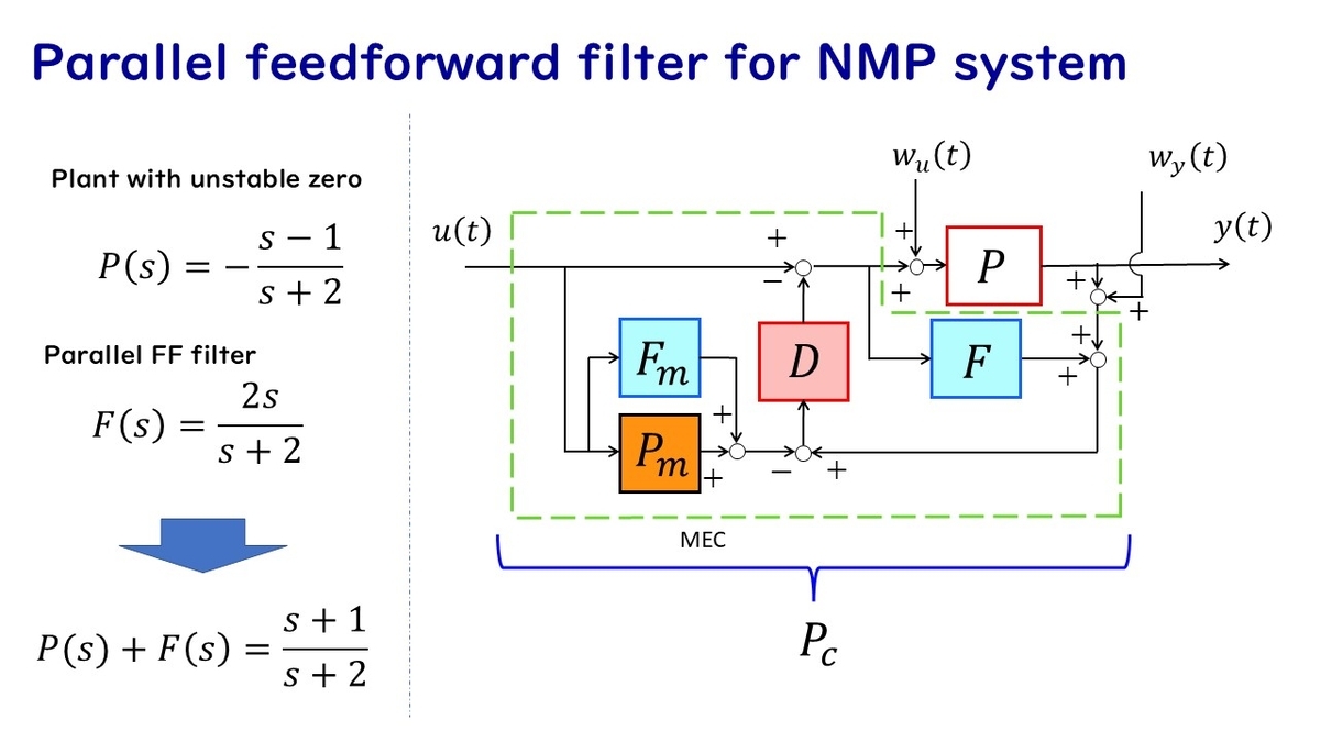
A non-minimum phase system is a system whose transfer function has zeros in the right-half of the complex plane (unstable zeros). For example, the transfer function:
with is non-minimum phase because it has a zero at
in the right-half plane. Non-minimum phase systems arise naturally in many practical applications, such as flexible structures, some aircraft dynamics, and systems with time delay (when approximated by Padé approximation).
The High-Gain Limitation
The basic MEC relies on high-gain feedback through the error compensator to drive the plant output toward the model output. For minimum phase systems, increasing the gain of
monotonically improves the model error suppression.
However, for non-minimum phase systems, the feedback loop between the plant and the error compensator (the "inner loop" of MEC) has an open-loop transfer function that inherits the unstable zeros of
. Due to these unstable zeros, arbitrarily increasing the gain of
can destabilize the inner loop. This is a fundamental limitation imposed by the non-minimum phase structure, not a limitation of the MEC framework itself.
The Solution: Parallel Feedforward Compensator
To overcome this limitation, a parallel feedforward compensator (PFC) is added in parallel with the actual plant. The PFC is designed so that the combined system
becomes effectively minimum phase, enabling high-gain error compensation.
MEC with Parallel Feedforward Compensator
Structure
The MEC with PFC has the following structure:
- Actual plant
— the non-minimum phase plant to be controlled
- Parallel feedforward compensator
— added in parallel to cancel or move the unstable zeros
- Modified nominal model
— the model is also augmented with the same PFC
- Error compensator
— the high-gain feedback compensator
The compensated control input becomes:
The error signal is now , which is the same model error signal as the standard MEC. The crucial difference is that the inner loop now involves
instead of
, and
can be designed to be minimum phase.
Design of the Parallel Feedforward Compensator
The PFC must be designed so that:
- The combined transfer function
is minimum phase (no unstable zeros)
- The effect of
The zero placement of depends on the choice of
. The JCMSI 2017 paper by Ichimasa et al. provides systematic design guidelines for choosing
to achieve minimum phase characteristics.
Design Methodology for Non-Minimum Phase MEC
Polytopic Uncertainty Framework
The JCMSI 2022 paper by Yoshida et al. extends the non-minimum phase MEC design to systems with polytopic-type uncertainties. The actual plant is assumed to belong to a polytopic set:
where denotes the convex hull and
are the vertex plants. The design goal is to find the error compensator
and the PFC
that guarantee robust performance for all plants in the polytopic set.
LMI-Based Design
The error compensator design is formulated as an LMI (Linear Matrix Inequality) optimization problem based on a common Lyapunov function. The design procedure consists of:
- Choose the PFC
minimum phase for all vertex plants
- Formulate the LMI for the error compensator
- Solve using iterative design or PSO — since the LMI is bilinear in the Lyapunov matrix and the compensator parameters, an iterative approach alternating between the two is used
Particle Swarm Optimization (PSO)
For the initial design or when the iterative LMI approach does not converge well, particle swarm optimization can be used to search for good error compensator parameters. The PSO result can then be refined using the iterative LMI design.
The MATLAB code implementing both the PSO and iterative design is available on GitHub (see MATLAB Code section below).
Comparison: MEC vs Disturbance Observer for Non-Minimum Phase Systems
A key advantage of MEC over the Disturbance Observer (DOB) for non-minimum phase systems is:
- DOB requires the inverse model
, which is unstable for non-minimum phase systems (the inverse has poles at the locations of the original unstable zeros). This makes the standard DOB structure difficult to apply.
- MEC does not require any inverse model. The PFC approach resolves the non-minimum phase issue within the MEC framework without introducing unstable elements.
For a detailed structural comparison between MEC and DOB, see Model Error Compensator vs Disturbance Observer.
Applications
Continuous-Time and Discrete-Time Systems
The JCMSI 2022 paper presents the MEC + PFC design for both continuous-time and discrete-time non-minimum phase MIMO systems. The discrete-time extension is important for digital implementation of the compensator.
Time-Delay Systems
Systems with time delay, when approximated by Padé approximation, become non-minimum phase. The PFC approach can be applied to these systems as well. The JCMSI 2017 paper by Ichimasa et al. specifically addresses MEC with PFC for time-delay and non-minimum phase plants.
Integration with Various Controllers
Just as with the standard MEC, the non-minimum phase MEC can be combined with any controller: PID, MPC, state feedback, feedback linearization, etc. The MEC + PFC is placed between the controller output and the plant input, independent of the controller design.
Connections to Related Research
Model Error Compensator: Comprehensive Guide — For the full overview of MEC including basic structure and design philosophy, see the MEC hub article.
MEC + PID Control — For the simplest integration of MEC with PID control (minimum phase case), see MEC + PID Control: Adding Robustness to the Most Widely Used Controller.
MEC vs Disturbance Observer — For a structural comparison with the Disturbance Observer, see MEC vs DOB: A Structural Comparison. The DOB's need for an inverse model makes it particularly difficult for non-minimum phase systems.
MEC for Nonlinear Systems — Nonlinear systems present another class of challenging plants for MEC. See MEC for Nonlinear Systems: Robust Feedback Linearization.
MEC Design with LMI — The polytopic uncertainty framework and LMI-based design used for non-minimum phase MEC is also applicable to minimum phase systems. The JCMSI 2021 paper provides the foundation: R. Yoshida, Y. Tanigawa, H. Okajima and N. Matsunaga, A design method of model error compensator for systems with polytopic-type uncertainty and disturbances, SICE JCMSI, Vol. 14, Issue 2 (2021) (Open Access).
LMIs and Controller Design — For background on LMI optimization in control engineering, see Linear Matrix Inequalities (LMIs) and Controller Design.
MATLAB Code
- GitHub (Polytopic MEC + Non-Min Phase): Robust-control-MATLAB_MEC01 — Includes
pso.mfor PSO-based design anditerative_design.mfor LMI-based iterative design. Thestable_nmp.matfile contains the non-minimum phase plant used in the JCMSI 2022 numerical examples. - GitHub (PFC for Time-Delay and NMP Systems): MATLAB_MEC03_withPFC
Related Articles and Videos
Blog Articles (blog.control-theory.com)
- Model Error Compensator (MEC): Enhance the Robustness of Existing Control Systems
- Model Error Compensator vs Disturbance Observer: A Structural Comparison
- Linear Matrix Inequalities (LMIs) and Controller Design
- System Identification: Obtaining Dynamical Model
- Discretization of Continuous-Time Control Systems
Research Web Pages (www.control-theory.com)
Video
Paper Information
Yoshida, H. Okajima and T. Sato, "Model error compensator design for continuous- and discrete-time non-minimum phase systems with polytopic-type uncertainties", SICE Journal of Control, Measurement, and System Integration, Vol. 15, Issue 2, pp. 141–153, 2022. DOI: 10.1080/18824889.2022.2052628 (Open Access)
Ichimasa, H. Okajima, K. Okumura and N. Matsunaga, "Model Error Compensator with Parallel Feed-Forward Filter", SICE Journal of Control, Measurement, and System Integration, Vol. 10, No. 5, pp. 468–475, 2017. DOI: 10.9746/jcmsi.10.468 (Open Access)
Related Japanese Paper: 岡島寛, 一政豪, 松永信智, 非最小位相系に対するモデル誤差抑制補償器の設計, 計測自動制御学会論文集, Vol. 51, No. 11, pp. 794–801, 2015.
Self-Introduction
Hiroshi Okajima — Associate Professor, Graduate School of Science and Technology, Kumamoto University. Member of SICE, ISCIE, and IEEE.
If you found this article helpful, please consider bookmarking or sharing it.